


Piston rings have such a tough job, mostly because of their working partners—namely oil and the cylinder they slide in. Anyone with some experience with sanding can appreciate that rubbing a coarse grit sandpaper on a rough surface takes force, generates heat and without a degree of “touch” (proper pressure, speed and stroke technique) can make things—well—rougher rather than smoother. Meaning, the surface you started to sand winds up with grooves, ruts and bumps that were unintended when you simply wanted smoother results. It gets easier, slicker and cooler when a lubricant is added to the equation; so-called “wet” sanding. Generally, there are fewer of those unintended consequences as well, but there’s still no guarantee. On many levels, the sanding analogy isn’t all that much different from what’s happening in a running engine—the engine is just a hell of lot more critical.
We already know the situation isn’t helped by the fact that rings, essentially, wind up operating in a goofy combination of wet/dry “sanding,” mostly the former in the middle of their stroke, but no doubt the latter when they change direction at the top and bottom of the stroke. So, we can see that there are at least two variables, beyond the obvious, that have quite an impact on the ability of the rings to do their job. One is the (damn variable) oil film. The other is the (more variable than you’d think) surface of the cylinder.
Oh!—Remember that heat generated by the “sanding” friction? Well, in your engine, it’s that heat/friction combo that imposes the 10-to-25-percent loss of power. Let me try to illustrate how delicate the balance can be with a story—a true story—involving the development of Harley’s (ultimately) wildly successful alloy XR750 in the early ’70s. Dick O’Brien, head of Harley-Davidson racing at the time, started out with pistons made by the same company used today, but with a couple of special features everybody thought would be the cat’s ass for a race engine—namely a reduction in piston crown circumference above the top ring and a fairly pronounced bevel on top of the ring itself. The ring groove was even more beveled, theoretically admitting more gas pressure behind the ring for a tighter seal when that was needed and allowing the ring to relax and coast for the three-quarters of the time when “max” sealing wasn’t required… equaling more power. That lower average friction was worth precisely one horsepower more at top revs, as it turned out. But the exaggerated clearance above the rings overheated the piston crown and the top ring groove! That let the ring move around too much which just made things hotter and—bottom line—power dropped off as the piston and rings deformed and died. Not that any XR750s blew up or melted down—they just didn’t make that extra horse after the first time in the “heat” of battle, and rings needed changing after every run—a tad too frequently to make power at all. A quick redesign and a lotta piston swaps later, you had XRs making a touch less power—for a lot longer. There’s a lesson in that. Namely, these are the kinds of trade-offs you’d sort-of expect, in that there is such a fine line between what works longer and what works better—sometimes only defined by priorities. For instance, a street engine you want to get 100,000 miles out of, before “re-ringing,” requires a compromise or two of its own, just as the race engine did. Yet, when it comes to optimizing the package overall, thinking has been surprisingly stagnant for a long time.
Since ring design is actually the least of our worries, let’s start by re-thinking some traditional notions about the cylinder instead. First, you should be aware of the curious fact that there is scarcely any difference in the quantity of heat removed by an aluminum cylinder and an iron one; heat transfer depends on the outer surface area in contact with the cooling medium—and the difference in temperature between the cylinder material and that medium—which for most Harley’s is—well—air! Of course, the advantage of aluminum is faster thermal conductivity and more uniform distribution of the heat through the metal. We know all H-D cylinders these days are aluminum—but—use an iron liner! With this little factoid in mind, along with the known differences in expansion rates of these dissimilar materials, let’s look at the main functions of cylinders/liners:
- Serves as the inner wall of a cylinder assembly, and forms a sliding surface for the piston rings while retaining the lubricant within. The most important characteristics of cylinder liner materials are: (1) excellent anti-galling properties, (2) reduced wear of the cylinder liner itself, (3) reduced wear on the partner piston rings, (4) controlled consumption of lubricant (more on that later.)
- Receives combustion heat through the piston and piston rings and transmits the heat through the liner/cylinder into the surrounding air.
- Prevents the compressed gas and combustion gas from escaping the combustion chamber.
To do all those things, it therefore follows that the damn things better hold the desired shape. They don’t do that as well as they could… even now. In the days of iron barrels, the wise guys would run a “green,” un-cured cylinder just long enough for it to assume something resembling its final heat cycled, “cured,” stable shape. Then they tore the top end off, bored the barrel over-sized and fitted new piston and rings. The outcome, almost invariably, was a faster, more durable motorcycle. We could learn from these old timers. They got that what’s critical to creating a perfect bore was roundness, straightness, surface finish and that all three qualities should remain consistent—in service—under all sorts of conditions.
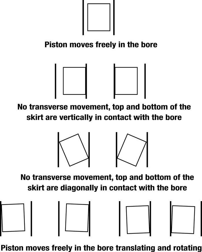
Here’s another; showing some of the more obvious and easy-to-check issues that could affect just how straight up and narrow your pistons and rings might be traveling… or not!
This condition isn’t so easy to spot without high-tech measuring tools. Either way, the thing to remember is that what happens on the bench does not stay on the bench, since a running engine is a dynamic system and subject to thermal loads that can change the shape of things to come—pistons, rings and barrel!
This li’l chart indicates (in exaggeration, of course) just how outta shape your barrels can be. And, that’s only one way of looking at it!
Until you get all that—Uh!—squared away, your piston will be doing the high-speed slug “jitter-bug” in three- quarter time, no less! It ain’t pretty!
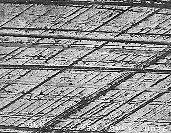
Here’s a 60x magnification of an up-to-the-minute plateau-honed cylinder. This is the “finish du jour” for now. What a laser (or some other technological contender) might do for ya tomorrow is pretty much up to you (and a good engine man) today.
Up till now the best prevention has been to “hatch” a plot like this; with 45-degree angled crisscross machine marks that hold oil on the walls and let the rings slide by. If only! (Fact is, this kind of surface finish, while useful for about a century, is liable to be obsolete before the next decades of this one.)
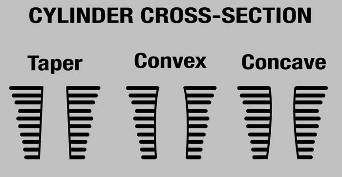
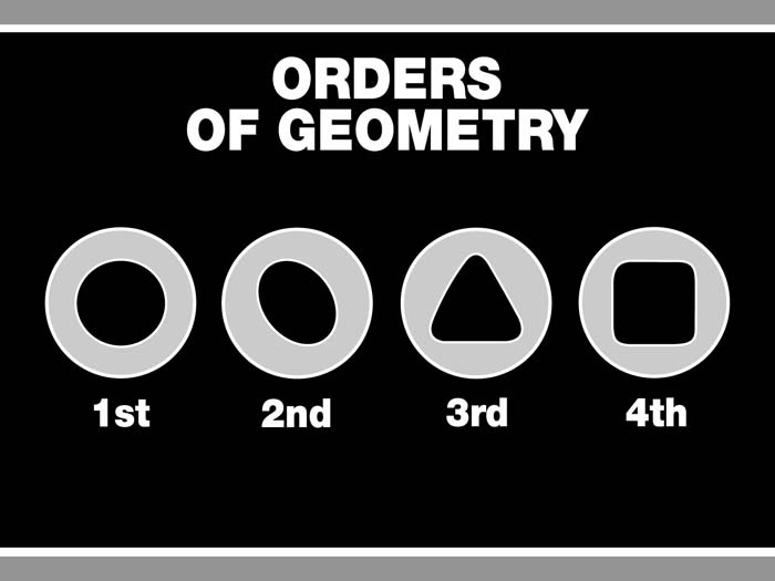
Sadly, bore distortion is still with us and can take many forms—so much so that the experts refer to bore distortion by what can best be described as levels of “order,” at least while looking down the hole. A first order bore is one that is perfect—round with no distortion in any direction. A second order bore is one with an oval distortion, typically caused by machining errors or heat transfer (we’ll get back to this one). A third order distortion results in a triangular-shaped hole (and is usually caused by a combination of second and fourth order distortions). A fourth order distortion is a bore with a cloverleaf or squared shape. This type of distortion is caused by the location (and heat-dispersing ability or lack of same in the vicinity) of the head bolts. The amount of distortion can vary from almost nothing up to a couple thousandths of an inch! With today’s tight piston-to-wall clearances, even 0.0005” of bore distortion may be too much on some applications, so the rounder the bore, the better. Rings can conform to the first two, concentricity and ovality, to some degree. However, taper and other distortions (from improperly torqued fasteners, inaccurate tooling, defects in manufacture and/or re-bores without torque plates, etc.) create “void” areas where contact is compromised, leading to lost ring seal.
That’s just where roundness and concentricity are concerned! We haven’t even addressed how “parallel” the cylinder walls need to—but might not—be! A straight hole is as important (maybe more so) as a round one and H-D barrels are no paragon of this virtue. Sadly, air-cooled alloy cylinders fitted with iron liners of disparate expansion rates and operating under various pressures, loads and temperatures shape shift—a lot! (In all fairness, that’s true of almost any air-cooled engine, not just a Harley V-Twin.) That doesn’t alter the fact that getting (and keeping) these things straight as the proverbial string ain’t easy, even though essential. While there’s generally very little conversation about how well fresh, new barrels fare, there are plenty of clues about how sophisticated and critical a re-bore and hone can be to basic “round and straight”!
Most of us are aware that factory cylinders cannot simply be yanked off the engine and (pardon the expression) “hogged” out. At least not the alloy stuff we’ve had since Evolution engines hit the scene decades ago. (Iron barrels probably shouldn’t be, but have been and still are bored bare-naked.) The main concern is fooling alloy cylinders into believing they are “in service” on an engine—in other words, clamped down tight in a tool known as a torque plate. More often referred to in the plural, as torque plates, the theory goes as follows: Bolt the cylinder into an appropriate set of these thick, strong plates and torque them down to approximately the same pressures the cylinder would experience as part of the engine. Makes for much straighter and rounder holes as well as more precision in the cutting of the oversize for new pistons and rings. As accepted practice it’s pretty damn good, but not perfect for a simple reason that might already be dawning on you.
You see, all that flipping, floppin’ and flexing by the pistons and rings in a running engine—not to mention the varying degrees of quantity and quality lubrication of same—in a very inconsistent operating environment (both within and without) means these finished bores don’t really stay finished. Because the dynamics in a running engine (friction, lubrication, ambient temperatures, velocities, etc.) can make a mockery of what happens “on the bench,” the real finishing is done by the loose nuts at the handlebars (us!) and is commonly known as “break-in.” (I really wish they could come up with a term for this process that did not include the word “break.” Point is; you get to do it with new and re-bored/honed cylinders—but the results are usually best with the latter.) All the same, before we worry about that, we have one more thing to attend to… well, two, really…
The final “texture” the piston, and more importantly the rings, have to contend with is the honed (not bored) so-called “cross-hatch.” Boring and honing are both becoming very complicated subjects as cylinder finishes become more refined and oils become more slippery, as we have sort-of just seen. For research into bore shape, the search for perfection requires sophisticated and precise measuring instruments to thoroughly measure and display the bore shape. Not the sort you’d have lying around the house, so needless to say this process is best left to pros—with the right tools—like an Inner Contour Meter such as Sunnen Corp. makes. Where it’s starting to get crazy is actually at the point where the crosshatch is applied… and you might want some insight or input into that. Typical crosshatch angles are 45 or 30 degrees, +/-5 degrees. (Lighter tension rings usually like the 30-degree crosshatch angle.) A steeper crosshatch provides a faster relief of oil, while lesser angles hold more oil. Another aspect is ring rotation, which is driven by steeper angles, so the lower angles are more appropriate with low-tension, thinner rings. Harley hasn’t come right out and said anything official for a while, but the “normal” crosshatch for our engines has been the 45-degree one. This might not be best in the future, for any number of reasons—not the least because crosshatch works in concert with surface finish (smoothness) and these two elements, in tandem, are being researched as we speak, for improvements in everything from power to durability and (tah-dah!) oil control. The most common of these processes are single-grit finish, multiple-step finishes and “plateau” finish. A single-grit finish is the simplest: You bore the barrel, and then hone it with one grit of a given abrasiveness. For a multi-step finish the walls are brought smoother and smoother in steps, such as going from 220, 280, 400, to fine 600-grit. A plateau hone amounts to a comparatively rough initial finish followed by a very fine finish, as goofy as that sounds. Yet, plateau hones are current state-of-the-art for Harleys, because this finish produces effective valley areas for lubricant retention, in conjunction with flat peaks that provide significant “bearing” area, which is easier on the rings. For high-performance engines, the plateau technique is still considered one of the best finishes. That said—it ain’t perfect, either!
Among the many potential alternatives, Federal Mogul is touting a new process called Helical Slide Honing, which involves the development and application of specialized honing abrasives (mainly of ceramic/diamond composition) so slide honing can generate a surface very close to the ideal plateau. However, one of the best notions in current thinking about future techniques is to use lasers, rather than primitive grinding equipment—not only to check the finish but to create it. For lack of a better way to describe what’s up with this, the end game would amount to a very smooth surface, on a very round and straight hole, that is essentially “pock-marked” with microscopic holes, rather than the ridges we have now. Up close, the metal the rings rub on would look a lot like—well—a golf-ball texture, only extremely tiny in pattern and effective in dispersion of the pattern. In other words these tiny dimples would appear in different sizes, depths and location on the walls, depending on their exact function at that point in piston travel, thus dealing with almost all of the issues we’ve covered, but mostly to “manage” the depth, motion, retention or even relocation (to spots where it will do more good) of that thin film of lubricant so necessary, yet so ephemeral. The day that sort of technology shows up on our machines is the day we see vast increases in smoothness, temperature control, longevity and horsepower!
But even then—the final act is ours—that break-in thing! We’ll talk about that—soon!


")


