Gear Driven Cam Kit #33-5177
S&S Cycle
$719.95
www.sscycle.com
608.627.1497
The inherent design flaw of Harley-Davidson’s cam chain tensioner system on their early Dyna and touring models equipped with the Twin Cam 88-inch motor is legendary. Horror stories of premature wear on the plastic facing of the tensioner shoe, the resultant scoring by these bits of plastic on the internal walls of the oil pump housing and reports of catastrophic engine failure were widespread. While The Motor Company stood by their product, many service departments suggested a maintenance check every 20,000 miles “just to be sure.” (There is no actual recommended mileage schedule to inspect the chain tensioners in the Harley service manual.)
I checked mine on my 2003 Road King for the first time right before riding to Sturgis last year with 42,000 miles on the clock (I don’t heed advice very well). After pulling the nose cone off and inspecting the outer (primary) tensioner, I realized that I’d have to get knee-deep into it to properly survey the wear on the inner (secondary) tensioner. My schedule was too tight for that type of delving so I buttoned it back up, hoping that the relatively good appearance of the primary tensioner (with less than 1/32″ of wear) would be a reflection of the secondary one. (I later found out that the inner, secondary tensioner usually fails first due to elevated operating temperatures.) With my ear constantly cocked to the side listening for abnormal cam cavity noises, the thought of the tensioners performing a self-destruction act and coughing up a nylon loogie persistently gnawed at my confidence. Such musings made it difficult to enjoy the road, the rally and the ladies. Something had to be done.
In 2006 Harley-Davidson completely redesigned the Twin Cam 88 in the Dyna models and introduced upgraded tensioners that replaced the spring-loaded design with a version using a hydraulic actuator. The hydraulic setup is now standard on all new models. That’s all well and good, but what about all us guys on older Twin Cams? S&S Cycle heard our cry and came to market with their Gear Drive Cam system. This product completely eliminates the dual chain drives and sprockets and replaces everything with a series of meshing gears that run off the motor’s crankshaft (or, as us old-timers used to refer to it, the pinion shaft).
Along with eradicating plastic debris contamination, additional advantages claimed by S&S Cycle include more consistent cam timing due to the elimination of variations between chain and tensioner; maintaining more accurate valve timing when using high performance valve springs; eliminating excessive side loading of cam bearings; and, since the rear gear-driven cam rotates in the opposite direction of a rear chain-driven cam (both cams are completely replaced with this kit), the lobes on the front and rear cams never point toward each other, allowing increased lobe height (i.e. higher cam lifts and more performance potential). Having cut my teeth on gear-driven cams (an ancient Shovelhead), I knew the simplistic design was damn near bulletproof. And bulletproof is close enough to idiot-proof, so I decided to try it out.
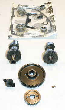
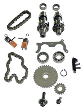
S&S Cycle offers five different cam arrangements that vary in valve timing, duration and lift. My TC88 is completely stock except for a decent set of mufflers and a much-improved breather so I opted for their 510G series that basically matches my motor’s cam configuration. Some of the more radical cam designs require checking valve-to-piston clearances and/or modifying the valve pockets in the pistons. Another reason for my choice of the 510G was economics. None of the other gear-driven camshaft kits are compatible with stock pushrods or valve springs. The complete S&S kit is PN 33-5177 and includes both 510G cams (with inner gears already mounted), an installation kit (PN 33-5163) containing all the needed gaskets and new bearings, the pinion drive gear and the outer cam gear. The S&S kit provides limited bolting (only the two flange bolts that attach the mainshaft and drive gears) but relies instead on the stock Harley fasteners.
I was tempted to tackle this project on my own in the security of my own shop. But that would have necessitated involving a photographer to document the process and the distasteful task of editing out all the plumber’s crack photos (my in-house photographer thinks he’s a comic and loves to sacrifice my dignity). So instead I opted to enlist the help of Greg Hale, proprietor of MC Creations in Northwest Houston (www.mccre ations.org). Greg is a well-recognized figure in the world of Texas motorcycling and works on everything from flatheads to the latest Milwaukee offerings. It’s not unusual to have to step over a freshly built Knuckle motor or squeeze through a stack of antique rigid frames just to get to the counter. (Greg is a big swap meet junkie.)
Greg linked me up with his top wrench, Shane Cole, and once I saw Shane’s personal ride—a big-inch, rigid rat Shovel that he races at the strip—I instantly knew he was my man. His only concerns centered on me getting in his way during the install or asking too many stupid questions. I promised him I’d do my best to stay invisible.
Shane started the project by disconnecting the battery and removing the pipes and mufflers. To keep from having to dismantle the top end, I had decided to junk my stock nonadjustable pushrods and replace them with a set of Screamin’ Eagle High Performance pushrods (#17997-99A) that include new covers, clips and O-rings. I even agreed to allow Shane to remove the stock pushrods with a… a… with a pair of bolt cutters. And damn, that was not easy to watch.
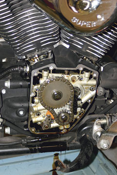
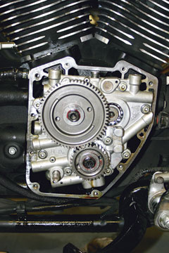
Next came the lifters, which Shane prefers to completely remove from the motor instead of securing them in place with a wire clip as is recommended in the H-D manual. (Just be certain to tag them so they make it back into their original positions—helps with the wear patterns.) Shane then removed the nose cone cover and “unloaded” the tension from the outside tensioner. With a quick zap of the impact gun, both the bottom pinion bolt and the rear cam bolt were free, allowing the crank sprocket, the cam sprocket and the primary cam chain to be removed as a unit. A handful of screws later and the cam support plate slid out of the cam chest cavity.
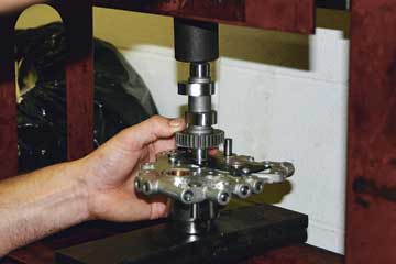
After removing the outside (primary) cam chain tensioner, the pressure on the inner (secondary) tensioner was relaxed and the bearing retainer plate removed. The cam support plate was then positioned securely in a hydraulic press and both the stock cams and bearing were pressed from the cam plate.
Wear on the faces of the tensioners was surprisingly modest for the number of miles they’d endured at the time of installation (46,550) with the primary tensioner having only 0.030″ of wear and the secondary showing 0.035″. Both were well within the specified factory limits of 0.080–0.090″. So maybe I had a good one, but then there were a few nasty chunks of material missing from both tensioners with the inside (secondary) unit suffering the worse pitting—I don’t even want to think about where that stuff ended up, hopefully in an oil drain pan or filter. But with this gear drive install, any future fears would be put to the side and I shouldn’t have to dig this deep into the Road King’s guts again for quite a while.
Early cam support plates used ball bearings on both the front and rear cams. But the cam chain tensioners exerted a large side load on the rear camshaft, which required redesigning the rear cam bearing to a roller bearing that was more capable of handling the load. The S&S Gear Drive Cams call for both front and rear bearings to be ball bearings since the OEM roller bearing has too much internal clearance, allowing the gear center distances to vary, resulting in excessive gear noise. New camshaft ball bearings are supplied in kit #33-5163, mentioned earlier. After pressing the new bearings into place, a new bearing retainer plate that is modified to provide additional clearance for the larger bearings is installed with a drop of blue Loctite on each screw which are then tightened to 20–30 in/lbs torque.
Since Shane was so deep into the motor at this point, I decided to also have the original cam case bearings replaced—especially since they were included in the kit. JIMS manufactures a specialty tool that makes both the removal of the old and the installation of the new a simple process. And although the installation instructions indicated that only the higher lift cam kits required a clearance check between the pinion bearing boss (in the case) and the rear cam lobe, Shane felt better checking both cams for clearance at this time. (I was liking this guy more and more.) He also checked the various O-rings in the oil pump and cam chest for brittleness, since they can be destroyed by an overheated engine.
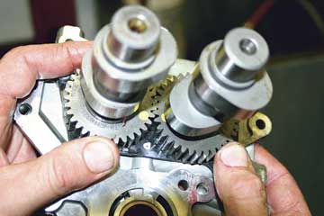
After applying assembly lube to the outer bearing surface of the front camshaft (the front cam is slightly shorter than the rear cam) and the inner race of the front bearing (in the support plate), the front camshaft is pressed into its bearing. A retaining ring is then installed on the outer end of the front camshaft. After lubing up the rear camshaft in a similar manner, “time” the rear cam by matching the timing marks on the front cam (both camshafts have a notch on their outer ends and alignment timing dots on the inside of their gears). Then press the rear camshaft into place. After applying a thin layer of assembly lube to the inside cam journals, the lobe surfaces and the inner (case) bearings, align the camshafts with the bearings and slide the cam support plate over the crankcase dowels. It should slide into place without resistance and should never be forced. Loosely install the six cam support plate screws with a drop of blue Loctite. Torque them in the proper sequence to 95 in/lbs (the Harley service manual states a maximum of 120 in/lbs can be applied but this amount of torque has resulted in stripped threads before). Next install the four oil pump bolts also with a drop of blue Loctite. Gently bottom out the screws and then back them out a quarter turn. Spin the rear wheel with the bike in gear (to turn the motor over) and “seat” or “center” the oil pump while snugging down the screws. Torque them in the proper sequence to 95 in/lbs. Then verify that everything rotates freely with no binding.
Next Shane placed the crankshaft gear on the crankshaft (pinion shaft) with the timing mark facing out. (There is a flat on the shaft so there is no way to screw up the install except to put it on with the timing mark to the inside.) He then applied red Loctite to the flange bolt threads and a small amount of oil to the underside of the flange to aid in assembly. Torque to 25 ft/lbs. Spin the motor over until the timing mark on the crankshaft gear is pointing toward the rear cam. Install the key in that portion of the rear camshaft that protrudes through the support plate and then slide the drive gear in place with the timing mark facing out and in alignment with the match-mark on the crankshaft gear. (This was the only point in the entire installation process where any part didn’t fit exactly. A small amount of hand filing on the key was needed for the gear to slide into place.) Once again use red Loctite on the cam gear bolt along with the special thick washer, both of which are supplied with the kit. Torque to 34 ft/lbs and, as is standard for any modification such as this, check for any binding.
All that was left was to fit the nose cone cover in place without a gasket and spin the motor to check for any interference (there was none) and then install the cover with a dry gasket. When I asked Shane about the lack of any needed gasket sealer, he replied, “We ain’t wrenching on yer Shovelhead, Robert. These Twin Cams are manufactured not to leak.” After torquing down the cover, Shane installed the lifters and the anti-rotation pins back into their proper openings and then the lifter covers. After assembling the new pushrod covers with new O-rings, Shane installed the new pushrods (long ones are exhaust), adjusted them to zero lash, tightened them down two and a half turns and then waited for the hydraulic lifters to bleed down. The final bits entailed installing the exhaust (with new gaskets) and the seat. After taking the bike out for a test run, Shane came back in and asked, “What’s the top speed you’ve ever hit on this bike?” I replied, “A buck 10.” He then went on to tell me it was capable of at least 119. He said there was a little throttle left but he didn’t want to overdo it. Staying on track as a true gearhead, Shane would rather something go wrong while he’s at the controls than have a mishap occur while the customer is on the highway.
The entire process took five hours. The S&S installation instructions were simple but precise and at no time left any gaps in explaining, in detail, the complete procedure. Looking back on it, except for the absence of a hydraulic press, I could have done the install myself in my own garage. But then it probably would have taken me a bit longer than five hours (I can be a bit anal about my motor wrenching). I ran the new gear-driven cam kit over the weekend for a couple hundred miles and then took off for a two-week, 3,800-mile trip to the Outer Banks region of North Carolina, down to the Florida panhandle and then back home to Texas. The bike seems a bit more snappy since the install (possibly due to quicker valve response or possibly due to my imagination and desire for it to be snappier). At no time has the S&S Gear Drive Cam kit given me any problems or given rise for any concerns. This speaks to both the quality of the product (thank you S&S) and the skill of the shop performing the work (thanks to MC Creations). The most noticeable difference is that when the bike gets up to full operating temperature, the motor does emanate a low-key whirling, blender-type sound from the cam area. But that is of small consequence when compared to the reassurance I now have. Reassurance that allows me to once again enjoy the road, the rally and all those ladies.