


Last month we discussed the notion of controlling air flow below the piston rings, i.e., in the crankcases of a motorcycle that suffers from a crankcase that’s too small to “breathe” easily. This includes all OHV Big Twins from 1936–on and specifically late-model Shovelheads and early Evos… typically referred to as “bottom breathers.” Evo head breathers, both Big Twins from 1993 and Sportsters, can benefit from the concept, but would employ slightly different methodology. We’ll deal with those machines later. For now, let’s stick to the early stuff… and some fundamentals before we get into details.
First—air compresses and oil doesn’t. Air has little inertia and oil has a lot. Simple enough to grasp in theory but evasive in practice. Apropos V-twin engines, it means you should never employ uncontrolled “open” breathing of air within the cases. Mostly, this is because you will never achieve oh-so-useful “negative pressure” (vacuum) in the cases when air is allowed to move back and forth whenever it wants as the engine runs. It’s also because air, while it can’t compress oil… can sure as hell interfere with it’s flow. Begs a question; there’s many a oiling system diagram, but have you ever seen an “airing” system diagram? Didn’t think so.
Second—as the cliché says, “an engine is a pump.” True, but not the whole story. Pumping efficiency above the piston rings (i.e., in the combustion chamber) determines power levels. Seems like a bazillion dollars are spent annually trying to improve the efficiency of internal combustion engines… up top. But little, if any, attention is paid to improving efficiency below the rings. I suppose this is because there’s scant recognition of its value, since efficient crankcase breathing won’t boost power notably. The flip side is, lousy case breathing means you never see all the power the engine is capable of… sustainably! And… it means high levels of blow-by, so-called “oil carry-over,” ring flutter, and gasket failures.
Third—oil pumps play a role in all of this that’s not well understood. Fact is, in a dry sump engine, like Harley’s, they go from not doing anything much at idle to being a controlling factor at high engine speeds… as we’ll soon see.
Fourth—air flow in the crankcases acts the much same way, allowing more blow-by at idle because low engine speeds mean (relatively speaking) lots of “dwell” time, allowing air to pass the rings, dragging as much as 67-percent oil and 12-percent water… with it! Whereas at red line the reciprocating parts aren’t giving air enough time to blow by much of anything. It’s the transitions from idle to red line that are of interest.
OK, the details are best left to be seen. So that’s next, after one other thing. You need to know what you’ll see is a work in progress… a “proof of concept” lash-up that will be refined. What the lash-up has accomplished so far indicates it does work… but not necessarily as predicted or planned. It’s no magic fix but a surprisingly effective “work around” for reasons discovered during initial testing. There will be more testing and refinement. The advantages of “tuned” air flow within the cases make it worthwhile, since blow-by is purged and over-pressure is prevented in “stages.”
Stage One—air flow valve function synchronizes with the engine opening and closing with the rise and fall of the pistons from idle to about 3500 rpm.
Stage Two—is a transitional one, from 3500–4000 rpm the engine starts to pass hotter gasses at higher pressures, both negative and positive. Net result is still a slight vacuum in the cases, but the engine is making the rules and air valves have to follow them. Here is when scavenging of both oil and air by the oil pump becomes an added and important factor!
Stage Three—tends to happen from roughly 4000 rpm. At this point both the in and out air flow valves are open all the time, because by then the engine is continuously pumping air pulsing above atmospheric pressure then going rapidly below it. The trick here is to use the size/capacity of the air flow valves to create a “bias” that ensures the difference in flow through them, relative to the demands of the engine maintains negative pressure in the cases. Here is where the factory rotary breather becomes an unwanted “gatekeeper.” The breather “window” in the timing case is set to operate as the piston nears bottom dead center (BDC)… weird because everything worthwhile happens in the first half of the downstroke. Fact is, the breather mechanism stays shut (or close to it) for something like 98 percent of engine rotation which means there’s just not much engine breathing available, except through the scavenge side of the oil pump!
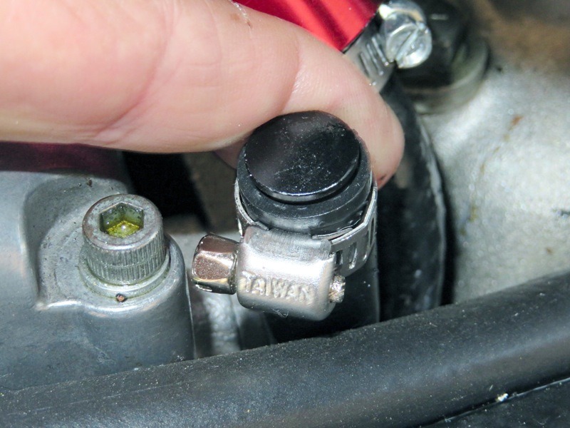
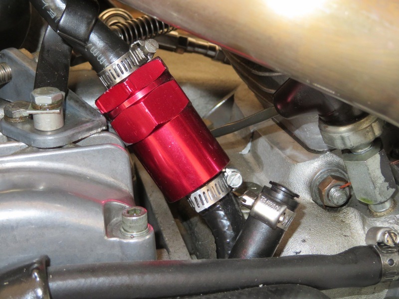
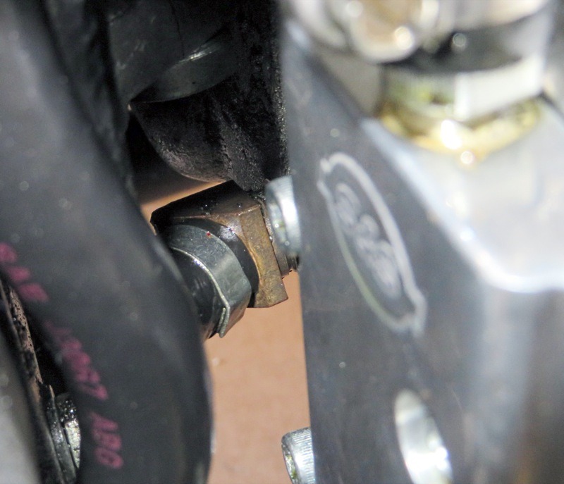
With that in mind, let’s set up the “exhaust” air breather. (The intake side we’ll get to next month.)


